FCAW Flux Cored Arc Welding Information
What is Flux Cored Arc Welding?
Flux core arc welding was introduced in the 1950's. Technically the introduction of this process was not new. It was just a new type of an electrode that can be used on a MIG welding machine. Flux cored arc welding is a process similar to MIG welding. Both processes using continues wire feeds, and similar equipment. The power supply for a FCAW, and a MIG welder, are the same machine. They are both considered semi automatic processes, and have a very high production rate.
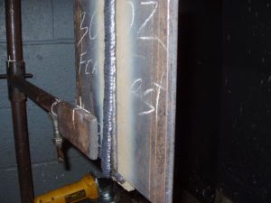
What is the Difference Between FCAW and MIG Welding?
The main difference between flux cored arc welding and MIG welding is the way the electrode is shielded from the air. Flux cored arc welding just like the name implies, has a hollow wire with flux in the center, similar to the candy called "pixy sticks". Just as the name states, a "Flux Core". The main difference between MIG welding and flux core arc welding is, FCAW gets its shielding from the flux core, and this allows the operator to weld outdoors where it is windy. It's like a SMAW welding electrode turned inside out! MIG welding gets its shielding from a bottle of gas which has serious drawbacks, when welding outdoors, or in drafty conditions.
How Long Does it Take to Learn Flux Cored Arc Welding?
If you already know how to MIG weld and can Stick weld in all positions all it takes is a few hours of practice to master FCAW welding. I literally practiced for 2 hours and passed a 3G Flux Cored Arc Welding Certification.
How Much Faster is Flux Cored Arc Welding?
Flux cored arc welding is the most productive of the manual welding processes! When comparing MIG welding to flux core arc welding, there is a huge gap in production, in the amount of weld per hour. A MIG welder can typically produce 5 to 8 pounds of weld per hour, verses a FCAW welder packing 25 plus pounds of weld per hour. On top of that flux core welding can weld 1/2″ plates in a single pass with full penetration on both sides. Flux core arc welding for this reason is primarily used in the shipbuilding industry. Ships are made of heavy plate, and have endless amounts of welding that needs to be done. Flux core welding produces high quality welds, fast, and even when in windy conditions.

What Can FCAW Weld?
Welding with flux core electrodes has some serious cons when it comes to the weldability of metals. So far, Flux Cored Arc Welding has been perfected on most carbon steels, cast iron, nickel based alloys, and some stainless steels. Unfortunately most non ferrous exotic metals cannot be welded and that includes aluminum. On the upside for most hobbyists the flux core electrode may be an excellent choice for general garage work, because if used in a MIG welder there is no shielding gas required on some electrodes.
How Flux Cored Arc Welding Works?
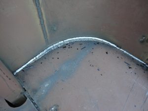
Flux cored arc welding just like MIG welding requires three main ingredients, electricity, filler metal, and a form of shielding from the air. Just like MIG welding, flux core welding works by feeding an electrode continuously to the joint. First the welder squeezes the trigger, and then the wire feeder begins to feed the electrode to the joint, at the same time the electrode gets electrically charged. Once the electrode hits the metal joint, the electricity short circuits, and heats up the electrode till the electrode begins to melt. Once the electrode begins to melt, the metal also starts to melt, and then both of them start to create a puddle. This puddle at the same time melts the flux core, creating a shield from air, and at the same time produces a slag that protects the weld from contamination.
What is the Difference Between Self-Shielding vs. Dual Shield FCAW?
Flux cored arc welding comes in two types of shielding. The first difference is in the electrode itself, it is a tubular wire with a shielding powder in the center. In technical terms this is called "Self-Shielding" or sometimes branded "Inner Shield". The second is the same type of electrode, but another ingredient is added. A bottle of gas is used in addition to the flux core shielding. The technical term for this is "Dual Shield". In the case of dual shielding, you have a powder flux in the center of the electrode and an external shielding gas protecting the weld area.
FCAW Voltage Type – Welding Polarity – Power Supply
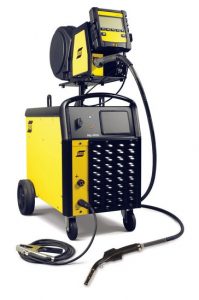
A flux cored welding power supply is also a MIG welding power supply, they are the same machine. That is a "Constant Voltage Power Supply". Constant voltage power supplies keep the voltage near, or at the same level. Unlike a TIG, or Stick welder, that keeps the amperage consistent. In the flux cored welder the amperage is changed with the wire feed speed. The faster the wire feeds, the more contact the electrode has, producing more amperage, and heat.
The voltage type used is DC direct current like the type current produced by a battery. The polarity used in industrial flux core arc welding is typically D/C electrode (+) positive. This means that the handle is the positive side of the circuit, or the electricity flows from the metal to the welding handle. This is typical when larger electrodes are used. When welding with smaller electrodes and sheet metals, the polarity is changed to D/C electrode (-) negative.
The main difference between FCAW, and a MIG welders are, flux cored arc welding power supplies are available with, much, more, power! Basically they are an extremely powerful MIG welder! Some flux core arc welders come with the capabilities of running over an extremely hot, 1000 plus amps! That is where they leave MIG welding in the dust for production.
What Shielding Gas is Used for Flux Cored Arc Welding?
If you are welding with a “self shielding” electrode you do not need any shielding gas. Self shielding electrodes work well in the wind and burn through mill scale, rust and just about everything so no shielding gas is needed.
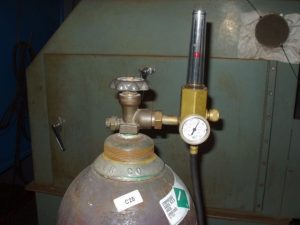
In the case of dual shielding being used with a flux cored electrode the choices of shielding gasses are limited. The choices are as follows:
- CO2 – Carbon dioxide
- Ar – Argon
- CO2 / Ar – A mixture of the two
- Ar / Ox (oxygen) – A mixture of the two
Weld Characteristics of CO2 Shielding Gas on Dual Shield FCAW
CO2 by itself produces the deepest penetrating weld but has some drawbacks. The mechanical properties of the weld are not the best due to fact the flux in the wire reacts with the shielding gas. Others drawbacks are, it produces a lot of spatter, and the arc is stiff and not as stable as it can be.
Weld Characteristics of Argon Shielding Gas on Dual Shield FCAW
Argon by itself will also weld with a flux cored electrode, but just like CO2, it reacts not favorable with the flux. Both Argon and Carbon dioxide can make a decent looking weld if used by themselves. What the weld looks like verses the actually quality of the weld are two different stories.
Weld Characteristics of C25 Shielding Gas on Dual Shield FCAW
The most common gasses used for dual shield FCAW are a mixture of Carbon Dioxide and Argon or Argon and Oxygen. The most popular is C25 / 25% Carbon Dioxide and 75% Argon. This gas produces a stable arc, less spatter, and allows more of a spray transfer of metal. I recently used this mixture when taking my 3G flux cored arc welding certification. In some other cases a mixture of Argon and Oxygen may be used. Oxygen in small percentages stabilizes the weld arc and improves the mechanical properties of the weld.
Ultimately if using dual shield it's always best to read the electrodes manufactures recommendations or ask you gas supplier for the proper gas.
What Types of Electrodes Can be Used with FCAW?
The electrodes used for flux cored welding are almost visually the same as a MIG welding electrode. The difference is that flux cored electrodes are tubular, or a hollow tube with flux in the center. MIG welding electrodes are solid metal.
Flux cored electrodes come in standard sizes. Some are the same size as most MIG welding electrodes but others are comparable to the thickness of a stick welding electrode. Here are some of the more popular sizes for standard industrial applications:
- .035
- .045
- .052
- 1/16
As with most electrodes there is a standard classification code or designation code, on the spool they come on. To understand the classifications better it is important to know some basics about where the classification codes are different.
A somewhat common flux cored welding electrode is the "E71T – 1". As with all electrodes the numbers and letters all mean something. There identifications definitions are as follows:
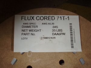
- E – Stands for electrode.
- 7 – Stands for the minimum amount of tensile strength. In this case it is 70,000 lbs of tensile strength per square inch of weld. The way this number is figured is by adding four zeros to the number.
- 1– Stands for the position that this electrode can be welded in. There are only two designations and they are "0" for flat and horizontal welding, then there is "1" for all position welding.
- T – Stands for a tubular electrode. When "T" is used it is always assumed it is a flux cored electrode.
- 1 – The last is the shielding flux type designations.
As a note with all flux cored electrodes they need to be stored in a dry place. Otherwise the may pick up moisture and this will cause major weld defects.
What Causes Worm Holes, Tracks and Porosity in FCAW?
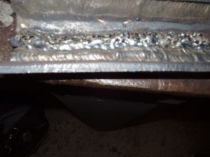
One of the most common issues when using Flux Cored Arc Welding wire is porosity, worm holes and worm tracks. What causes these defects is improper storage of the electrode. The electrode picks up moisture inside the wire and when the welder starts welding it creates wormholes, porosity and worm tracks. The way to fix this is cut off at least 10 feet of the electrode and then start welding. To avoid these issues the electrode needs to be stored in a dry place or a moisture proof bag.
Flux Cored Welding Transfer Types
When welding with a flux cored electrode there are two metal transfer types used! The transfer types are Spray Transfer and Globular. Spray transfer is the most commonly used. Just like the name states the metal from the electrode gets heated up to the point that it literally sprays the filler metal to the joint. Globular transfer heats up the electrode hot enough for globs of metal to drip off of the electrode to the weld joint. What separates the two transfer types are, voltage settings, wire speed, and the gasses used, if any.
How to Prepare a Weld Joint for FCAW?
Joint preparation for flux core is not as critical as with MIG welding. FCAW can typically burn through mill scale and minor rust. In many cases when the metal is cut with a torch, it can be welded as-is, with no additional cleaning. For the shipbuilding industry this is a huge savings in labor cost. In addition to easy joint preparation, beveled grove joints can be narrower for metals ½ inch or thinner, and they can be welded in a single pass with full penetration on both sides.
How to Weld with Ceramic Backing Tape?
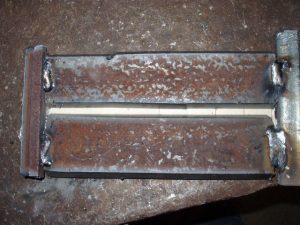
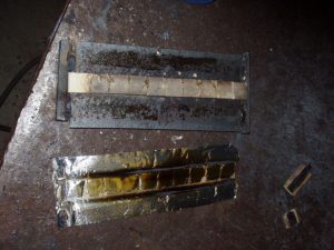
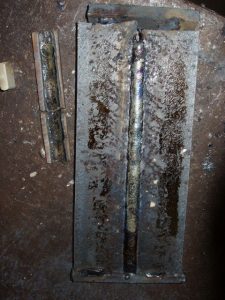
Commonly used in the ship building industry many joints are welded from a single side using a ceramic backing tape. Ceramic backing tape is a open root weld that is super easy to do. The ceramic backing tape is like a mold to pour metal in, but in this case the electrode will fill that mold. When ceramic backing tape is used it allows for full joint preparation and outstanding weld quality. This in return gives full control of the shape and penetration of the back side of the weld.
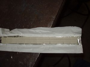
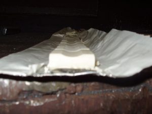
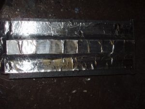
Once the weld is finished, the ceramic tape is simply peeled off, and thrown away. The great think about using ceramic backing tape is that it is just like welding an open root butt joint, but requires much less skill! The pictures below are of the first time I used ceramic backing tape on a 3G weld joint. The trick to using ceramic backing tape is to push as much weld into the joint as you can. There are no issues with over penetration and the worst happens your puddle size grows. It’s real easy as long as you keep the arc in the puddle!
How to Setup a FCAW Machine?
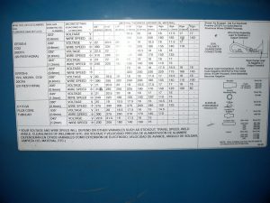
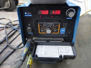
When setting up a for flux cored arc welding machine there is no simple answer! The basics of flux cored machine set-up are the same as MIG welding. On some welding machines like the Millermatic 250, there is a welding machine setting chart on the inside panel. The picture on the left is the inside panel of the Millermatic 250, showing the recommended voltage settings, wire feed speed, for the the metal thickness range. As the picture shows there are two main ingredients, they are voltage settings, and wire feed speed. The voltage setting controls the voltage and when choosing them it is best to use the electrodes manufactures voltage recommendations. When choosing a voltage ranges there are two factors that determine it, electrode size, and metal thickness. After that you can fine tune your settings to your comfort level. The wire feed speed setting is what controls the amperage and many times the transfer type. The faster the wire feeds to the joint, the more contact the wire has, and that increases the amperage. Most of the time you want the sound of the weld to have a fast deep crackle to it. This is very important when welding overhead! The overhead position needs the wire speed feed fast enough to avoid globs being formed. If globs start forming on the end of the electrode, you will soon find the nozzle getting filled with spatter, and chances are you will find some of that spatter burning you!
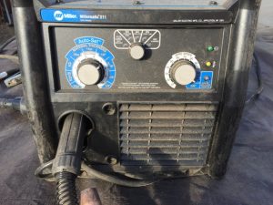
The machine above is a MillerMatic 211 and the new machines only require setting the dial to the right metal thickness and playing with them. The new machines are becoming very easy to set but it’s always good to know how to set you machine properly.
How to Set Up Shielding Gas for Dual Shield FCAW?

There is sometimes a third ingredient when the flux cored electrode is a dual shield type electrode. That is the gas flow rate for the shielding gas. This varies for the type of wire size used, cup size, and windy conditions. On my 3G FCAW Welding certification I used around 30 CFH in a classroom setting. But other times when welding in drafty conditions I had to go as high as 60 CFH on the gas setting.
How to Convert a MIG Welder to FCAW?
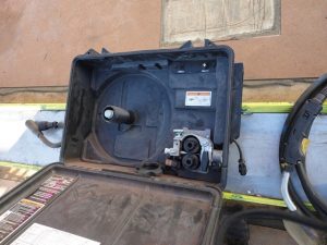
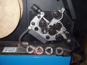
In the case the welding machine used is a MIG welder; the rollers need to be changed to the proper size. In addition to the proper roller size, the tension settings on the rollers should not be too tight. Otherwise the electrode will get crushed in the rollers and cause problems in the weld.
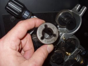
When setting the tension of the rollers they should be loose enough that it is easy for the rollers to slip when the wire is stopped. On the other hand the tension should be tight enough to keep the wire feeding to the joint without any disturbing the wire speed allowing a stable arc. Don't forget the tip, nozzle, and liner (if needed).
Flux Cored Arc Welding Techniques
Before trying to weld with the flux cored electrode, first you need to know the designation on the label. Remember flux cored electrodes come with two position designations. First is "0" and that's for flat and horizontal welding ONLY! The second designation is "1" and that is for all position welding! Always know what the electrode is designed to do.
FCAW is very similar to MIG welding when it comes to welding techniques! The main difference is how the puddle looks and the fact that welds are covered in flux much like stick welding.
Back Hand vs Forehand Welding
The first thing to consider is if you need to weld backhand or forehand. Either technique can be used for any position and remember these are just guidelines!
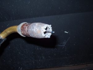
Back hand welding is when the handle of the welder is dragged like a Stick welder. The back hand technique is common for flux core welding in the flat and horizontal positions. The only other time you may want to consider the back hand technique is when welding in the 4G position. The reason for this is to avoid getting spatter on yourself. I tried welding a groove weld in the overhead position using the forehand technique and quickly got burned by a few sparks that got inside my leather. The picture above shows the spatter the nozzle got from welding in the overhead position, this is typical, and unavoidable. The down side of back hand welding is that the weld puddle is a little harder to see.Also when welding overhead the machine setup must be perfect! If you are less experienced you may find you weld wonders off of the weld joint without knowing it. You typically focus on the weld puddle size behind the crater just like stick welding. This method produces a very deep penetrating, high, and narrow weld.
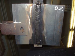
This picture above is a weld I did in the 4G position, even though the back hand technique produces a high weld, they look pretty much like it was welded in the flat position. The forehand method is when the welding handle is pushed in the direction of the travel. This method is typically used on thinner metals, in the vertical up, and for overhead fillet welds (4F). The forehand method also work well in the flat or horizontal position. This method of travel makes seeing the weld puddle easy. This allows you to see the weld joint easier and the chances of wandering off of the joint are not very likely. The down side of this technique is spatter can sometimes become excessive if the travel angle is not right.
How Much Should FCAW Electrode Stick Out Be?
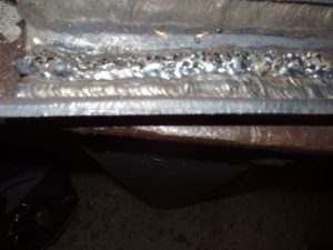
When FCAW the electrode extension or stick-out is greater when compared to MIG welding. MIG welding requires the electrode extension to be typically ¾ of an inch or less; otherwise the shielding gas won't do its job. With dual shielding the ¾ or less stick-out does apply in many situations. When FCAW with a self shielded electrode, extension should be kept about ¾ of an inch or more, depending on the type, and side of the electrode. In many cases the extra electrode stick-out pre-heats the electrode. This in return help dry off the flux inside the wire, and prevents much of the moisture the flux may have absorbed in storage from contaminating the weld. The picture on the right is a flux core weld done on a scrap metal, with to short of a stick-out, and some moisture in the wire resulting in weld porosity.
When it comes to flux core welding techniques there are no simple answers. Most of the techniques are the same as with all welding processes. For instance the whip of the weld, doing circles, and weave techniques used for wider welds. When it comes to doing wider weave welds, it is the least common. Most flux core electrodes are typically designed for stringer beads. Many times on wider welds the flux will peel off by itself without chipping. The pictures below are the cap of a 3G weld done using dual shielding, C25 gas, and E71T-1. All it takes is just a tap with a chipping hammer and the flux just drops to the floor!
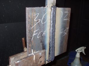
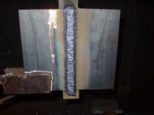
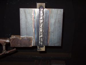
The angles to weld in different positions are similar to MIG welding! What changes when using flux core welding is a combination of many different factors like, electrode types, flux types, shielding gas (if any), and the thickness of the metal welded! It comes down to practicing with a specific type of electrode, on the same thickness of metal, by using a trial and error method. What works with one electrode type and metal thickness, may not work with another. I have personally found that welding overhead requires a perfect angle, and a precisely set-up machine in order to get the job done. The overhead angle is about 10 degrees, no matter if the method is forehand or backhand. Otherwise it will seem like it is impossible to get a good weld. All of the other positions are not as critical when it comes to travel angle. Just like any other welding process it is best to take a piece of scrap metal similar to the piece to be welded and do a quick practice run before welding!
Overview of Flux Cored Arc Welding
The reality of flux core arc welding is using a typical MIG welding machine and mostly the same equipment, with a few small exceptions! Although they are considered two different types of welding processes, it is only the electrode type, and shielding type, that separate them. Learning and understanding flux core welding is about learning to use a different type of electrode in a MIG welding machine. That is all there really is to flux core arc welding.
Next TIG Welding